


XY-LJ02 Timer Relay Delay Switch Module Delay Power Off and Trigger Delay Cycle Timing Circuit Switch with LCD Digital Display
- Relay module delay power off and trigger delay cycle timing circuit switch
- Timing Range:0.01 sec~9999 min
This product's LCD display is very clear, simple and easy to use, powerful, but please read user instructions carefully before using it.
Product Highlights:
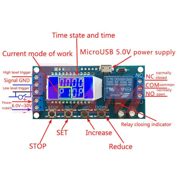
- Display with LCD two columns Can display parameters directly
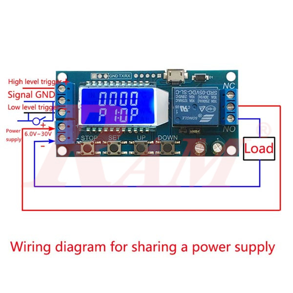
- Power supply: 6~30V, also supports micro USB 5.0V, very convenient.
- Anti-back connection of power supply.
- Trigger mode: high and low level, switch quantity.meet most of the needs.
- Parameters can be modified via UART.
- Stop button to provide emergency stop function.
- 5 minutes without any operation into a low-power state. Any action wake up.
- OP/CL/LOP params can be modified individually
- All parameters are automatically saved by power off.
Working Mode Introduction - Programs (P1~P7)
- P1: After the signal is triggered, the relay conduction in OP time then disconnects; In the OP time, the signal is invalid.
- P2: After the signal is triggered, the relay conduction in OP time then disconnects; In the OP time, the signal triggers a new timer.
- P3: After the signal is triggered, the relay conduction in OP time then disconnects; In the OP time, signal trigger reset timer, relay disconnected and stop timing.
- P4: When triggered, After the relay is disconnected from CL time, relay conduction OP time, after timing is complete, disconnect relay.
- P5: When triggered, After the relay conduction op time, the relay disconnects the CL time, and then loops the above action, gives the signal again in the loop, relays disconnect, stops the timer, and the number of cycles (LOP) can be set..
- P6: When triggered, After the relay conduction op time, the relay disconnects the CL time and then loops the above action, signal is invalid in the loop, the number of cycles (LOP) can be set
- P7: Signal hold function: The signal is maintained, the timing is cleared, and the relay conductsion; when the signal disappears, the relay disconnects after the timing OP; during the timing, there is another signal and the timing is cleared.
Product Parameters:
- Power Supply: 6V~30V and micro USB 5.0 V
- Trigger signal source: High level(3.0V~24.0V),Low level(0.0V ~0.2V),Switch signal.
- Maximum Output load: DC 30V 5A and AC 220V 5A.
- Static Current: 15mA Operating current: 50mA.
- Service life: more than 100,000 times; working temperature: -40-85°C; size: 8.0*3.8*1.9cm.
- Optocoupler isolation, Strong anti-interference ability, Industrial-grade circuit board
Timing Range: 0.01 sec~9999 min How to choose the timing range:
- In the OP/CL parameter modification interface, press the STOP button shortly to select the timing range.
- XXXX Timing range:1sec~9999sec
- XXX.X Timing range:0.1sec~999.9sec
- XX.XX Timing range:0.01sec~99.99sec
- X.X.X.X Timing range:1min~999.9min
For example, if you want to set the OP to 3.2 seconds, move the decimal point to ten digits. LCD display 003.2 Parameter Description: OP on-time, CL off time, LOP cycle times (1 - 9999 times, "----" represents an infinite number of cycles) Parameter Settings:
- Press and hold the SET key to enter the setting interface.
- First set the working mode, work mode flashes reminder, set the working mode by pressing the UP / DOWN keys.
- Short press the SET button to select the working mode and enter the system parameter settings.
- In the system parameter setting interface, press SET key to switch the system parameters to be modified, and press / long press UP/DOWN key to modify. (Note: Short press SET in P-1~P-3, P-7 mode is invalid).
- In the OP/CL parameter modification interface, short press STOP to switch the timer unit (1s/0.1s/0.01s/1min).
- After all parameters are set, press and hold the SET button for more than 2 seconds to release the hand, save the parameter settings and exit the setting interface.
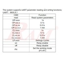
The system supports UART parameter reading and writing functions: UART:9600,8,1

Additional Features:
Low-power state: In the running interface, by pressing the STOP button for a long time, the Low-power function is started or closed (L-P selects on to start the hibernation function, and off turns off the hibernation function). Relay function selection: In the operation interface, by pressing the STOP button shortly, the relay function is started or closed, 'on' meets the conduction condition relay normally turns on, 'OFF' meets