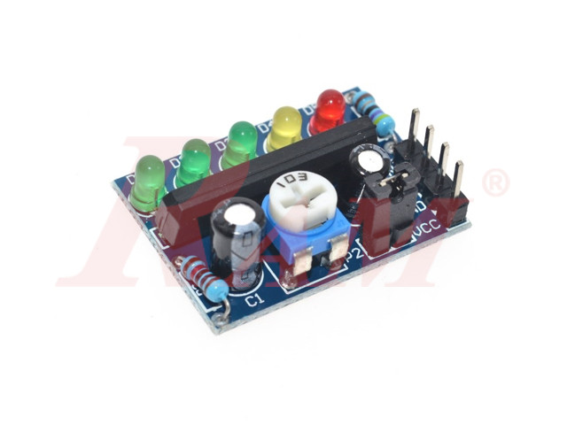
Battery Power level indicator (SKU#KA2284)
Battery Indicator Pro Audio level indicator module
Internal Reference:
KIT.INDICATOR.KA2284
The KA2284 Power Level Indicator Module is a versatile module commonly used for monitoring power levels, audio signal levels, or battery voltage levels. Here’s a general guide on how to use it:
Specifications:
- Operating Voltage: 3.5V - 12V DC
- 5 LED Indicators: Represent different levels (e.g., battery voltage, audio level, or power level).
- Signal Input: Analog input for voltage or audio signals.
- Adjustable Sensitivity: Through a potentiometer on the module.
Steps to Use the Module:
1. Wiring the Module:
- Power Supply: Connect the module’s VCC and GND pins to a DC power source (3.5V to 16V).
- Signal Input: Connect the IN pin to the voltage source or audio signal you want to monitor.
- For battery monitoring: Connect the battery’s positive terminal to IN.
- For audio signal: Connect the signal line (e.g., from an audio output) to IN.
2. Adjusting Sensitivity:
- Use the onboard potentiometer to adjust the sensitivity or threshold of the LEDs.
- Turn clockwise to increase sensitivity (LEDs will light up at lower input levels).
- Turn counterclockwise to decrease sensitivity.
3. Interpreting the LEDs:
- Each LED represents a different level of the input signal.
- For example, in battery monitoring, the LEDs indicate increasing voltage levels.
- In audio level monitoring, the LEDs indicate the amplitude of the audio signal.
4. Testing the Module:
- Power the module and provide an input signal.
- Observe how the LEDs light up based on the input signal level.
- If connected to a battery, higher voltage lights more LEDs.
- If connected to an audio source, the LEDs will react to the signal's amplitude in real time.
5. Applications:
- Battery Indicator: Use to show the charge level of a battery.
- Audio Level Indicator: Display audio amplitude in audio equipment or amplifiers.
- Power Level Indicator: Monitor voltage levels in circuits or devices.
Example Setup for Battery Monitoring:
- Connect VCC and GND to a 12V DC power supply.
- Connect the positive terminal of the battery to the IN pin.
- Adjust the potentiometer so that the LEDs accurately represent the battery levels.
Notes:
- Ensure the input voltage does not exceed the module's maximum rating (14V).
- For audio signals, you may need a resistor or capacitor to filter the signal for better accuracy.
- Avoid reversing polarity when connecting the power supply or input signal.
Download
Your Dynamic Snippet will be displayed here...
This message is displayed because youy did not provide both a filter and a template to use.
