GY-AMG8833 Infrared Thermal Imager Sensor Module
Non-Contact Infrared Thermometer
8x8 Thermal Camera Sensor
Internal Reference:
KIT.AMG8833.IR.IMAGER
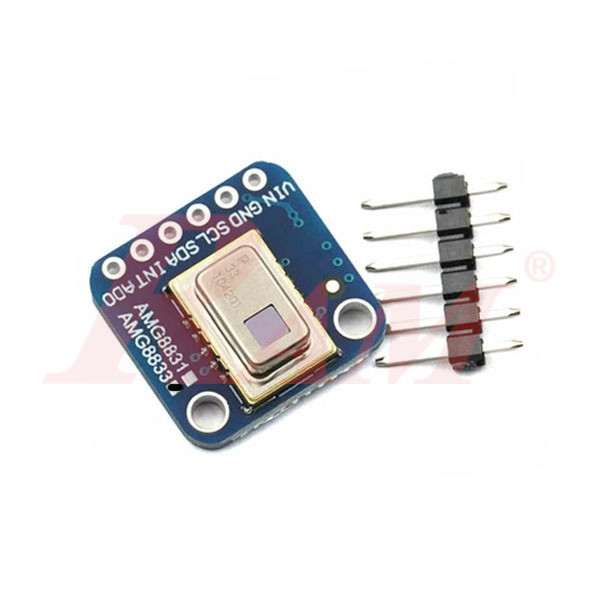
AMG8833 IR 8*8 Thermal Imager Array Temperature Sensor Module is an 8×8 array of IR thermal sensors. When connected to your microcontroller (or Raspberry Pi) it will return an array of 64 individual infrared temperature readings over I2C. It’s like those fancy thermal cameras, but compact and simple enough for easy integration.
Key Features
- Resolution: 8×8 pixel grid (64 pixels total)
- Temperature Range: 0°C to 80°C (32°F to 176°F)
- Accuracy: ±2.5°C (±4.5°F)
- Field of View: Approximately 110° × 75°, suitable for wide-angle, close-range measurements
- Detection Distance: Up to 7 meters (23 feet) for human presence
- Frame Rate: Up to 10 Hz
- Operating Voltage: 3.3V to 5V DC
- Communication Interface: I²C
Pin Description :
Power Pins:
- Vin – this is the power pin. Since the sensor uses 3.3V, we have included an onboard voltage regulator that will take 3-5VDC and safely convert it down. To power, the board, give it the same power as the logic level of your microcontroller – e.g. for a 5V micro like Arduino, use 5V
- 3Vo – this is the 3.3V output from the voltage regulator, you can grab up to 100mA from this if you like
- GND – common ground for power and logic
Logic pins:
- SCL – this is the I2C clock pin, connect to your microcontrollers I2C clock line. There is a 10K pull-up on this pin and it is level shifted so you can use 3 – 5VDC.
- SDA – this is the I2C data pin, connect to your microcontrollers I2C data line. There is a 10K pull-up on this pin and it is level shifted so you can use 3 – 5VDC.
- INT – this is the interrupt-output pin. It is 3V logic and you can use it to detect when something moves or changes in the sensor vision path.
Download:
- Code and Wiring: Click Here
Your Dynamic Snippet will be displayed here...
This message is displayed because youy did not provide both a filter and a template to use.