Product Description
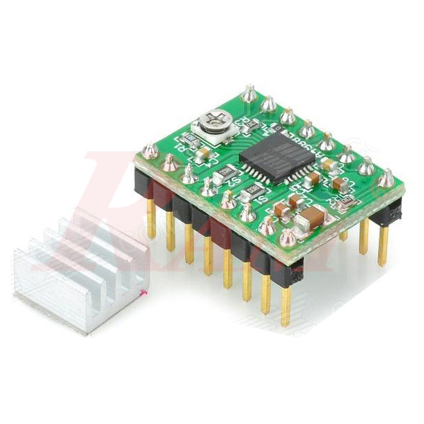
The A4988 Stepper Motor Driver Module is a widely used, high-performance microstepping driver IC designed for controlling bipolar stepper motors. Built on a compact green PCB, this module features built-in translator technology for simple step and direction control, drastically reducing the micro-controller processing power needed to operate motor positioning.
Equipped with adjustable current limiting, over-current protection, thermal shutdown, and five selectable microstep resolutions (down to 1/16-step), it is an essential component for 3D printers (such as RepRap/RAMPS), CNC machines, robotic arms, and precise DIY automation projects.
Key Features
- Simple Step & Direction Control: Enables easy driving with minimal GPIO pins from microcontrollers like Arduino, Raspberry Pi, or STM32.
- 5 Microstep Resolutions: Supports Full-step, 1/2-step, 1/4-step, 1/8-step, and 1/16-step modes for smooth and accurate motor movement.
- Adjustable Current Control: Integrated potentiometer allows precise adjustment of maximum motor output current to protect motor windings.
- Intelligent Chopping Control: Automatically selects the correct current decay mode (fast or slow decay).
- Built-in Circuit Protection: Includes thermal shutdown, under-voltage lockout (UVLO), and crossover-current protection.
- Includes Aluminum Heat Sink: Includes a dedicated adhesive aluminum heat sink for enhanced thermal management during continuous load conditions.
Product Specifications
- Driver IC: Allegro A4988
- Operating Voltage (Logic): 3.0V – 5.5V DC
- Motor Drive Voltage: 8V – 35V DC
- Continuous Current per Phase: 1A (without external active cooling)
- Maximum Current per Phase: Up to 2A (with heat sink and forced air cooling)
- Microstep Resolutions: Full, 1/2, 1/4, 1/8, and 1/16
- PCB Color: Green
- Module Dimensions: ~15 mm x 20 mm
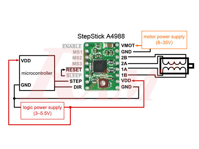
Pinout & Wiring Configuration
- Control & Logic Side:
- ENABLE: Logic Low enables output drivers; Logic High disables them.
- MS1, MS2, MS3: Microstep resolution selection inputs (pull HIGH/LOW to set step resolution).
- RESET: Pull LOW to reset internal translator logic (connect to SLEEP pin for normal operation).
- SLEEP: Pull LOW to enter power-saving sleep mode.
- STEP: Inputs pulse to advance motor by one step/microstep.
- DIR: Sets rotational direction (HIGH = Clockwise / LOW = Counter-Clockwise).
- VDD: Logic supply voltage (+3.3V or +5V).
- GND: Logic Ground.
- Power & Motor Driver Side:
- VMOT: Motor power supply (+8V to +35V DC).
- GND: Power supply ground (must be common with motor supply).
- 2B, 2A: Output terminals for Stepper Phase B coils.
- 1A, 1B: Output terminals for Stepper Phase A coils.
Microstep Selection Table
| MS1 | MS2 | MS3 | Microstep Resolution |
| LOW | LOW | LOW | Full Step |
| HIGH | LOW | LOW | 1/2 Step |
| LOW | HIGH | LOW | 1/4 Step |
| HIGH | HIGH | LOW | 1/8 Step |
| HIGH | HIGH | HIGH | 1/16 Step |
Important Note: Never connect or disconnect a stepper motor while the driver is energized. Doing so can cause permanent damage to the A4988 driver IC.