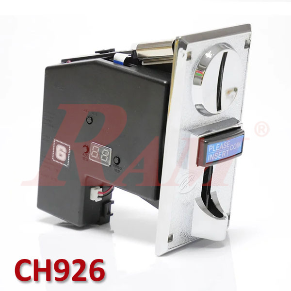


CH926 Multi Coin Acceptor Coin Selector Multi-Currency Can Accept Six Kinds for Slot Machine Gambling Game Arcade Cabinet
Description:
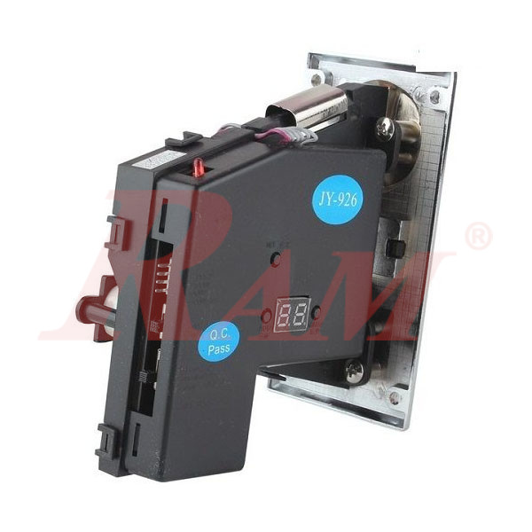
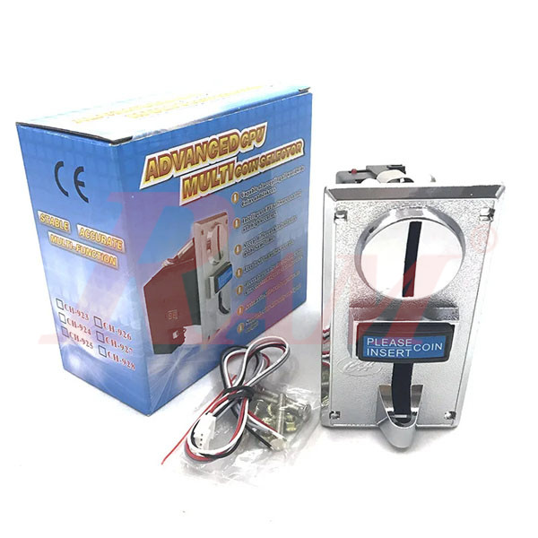
The CH-926 is a reliable, programmable, and versatile coin acceptor capable of recognizing up to six different types of coins or tokens. It features quick recognition, high accuracy, and can be programmed without the need for a PC, making it ideal for arcade machines, vending systems, and other automated payment applications.
Technical Specifications:
- Coin Diameter: 15 mm – 32 mm
- Coin Thickness: 1.2 mm – 3 mm
- Working Voltage: DC 12 V ± 10%
- Working Current: ~65 mA ± 5%
- Max Momentary Current: Up to 350 mA (for bursts <0.5 s)
- Recognition Speed: ≤ 0.6 s per coin
- Accuracy Rate of Identification: ~99.5%
- Operating Temperature: –15 °C to +50 °C
- Humidity: ≤ 95%
- Atmospheric Pressure: 86 kPa – 106 kPa
- Dimensions: ~170 × 130 × 70 mm
- Weight: ~365 g
- Material: Metal and PVC shell
Key Features:
- Accepts up to 6 different coins or tokens
- Self-programming with onboard buttons and LED display (no PC required)
- Customizable pulse output (up to 50 pulses per coin)
- High resistance to electrical and electromagnetic interference
- Automatic self-test diagnostics
- Suitable for arcade games, vending machines, massage chairs, kiosks, and more
CH-926 Coin Acceptor – Pin Assignment
-
DC 12 V (Power Input)
- Red wire — connect to a stable 12 V DC power supply.
-
GND (Ground)
- Black wire — common ground; must be connected to both the coin acceptor’s power supply ground and the microcontroller (e.g., Arduino) ground.
-
COIN (Pulse Output)
- White wire — outputs pulses per accepted coin. It functions as an open-collector (or open-drain) signal.
-
Requires a pull-up resistor (commonly 10 kΩ) to a logic-level voltage (e.g., 5 V). One end of the resistor connects to 5 V, and the other goes to both the COIN pin and a digital input pin on your microcontroller (for example, D2 on Arduino)
-
COUNTER (Grey wire)
- Not commonly used; purpose is unclear in typical setups. Best left disconnected unless specified by your hardware documentation.
Parameter Overview & Programming Procedure
Summary Table
Step | Action | What You Do |
|---|---|---|
| 1 | Enter Setup | Press Add + Minus (~3s) to display “A” |
| 2 | Set Coin Count | Setup → “E” → Select 1–6 coin types → Setup |
| 3 | Samples per Coin | “H” step → Choose sample count → Setup |
| 4 | Pulses per Coin | “P” step → Set pulses (1–50) → Setup |
| 5 | Accuracy | “F” step → Set level (1–30) → Setup |
| 6 | Repeat | Return to “A”, repeat for each coin type |
| 7 | Save Config | Setup → “E”, then power-cycle |
| 8 | Sampling | Setup twice → “A1” → Insert samples → proceed through A1, A2... |
| 9 | Finalize | After sampling, Setup → “A” → power-cycle to activate |
Your Dynamic Snippet will be displayed here...
This message is displayed because youy did not provide both a filter and a template to use.