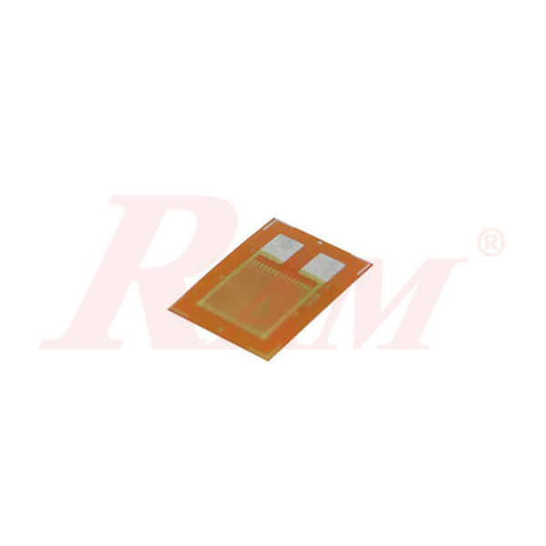
BF350-3AA Precision Resistive Strain Gauge
Internal Reference:
SEN.BF350
Model: BF350-3AA Constantan Metal Foil Strain Gauge
Basic Specifications
- Fatigue Life: ≥ 1 million cycles
- Resistance: 349.8 ± 0.1 Ω
- Gauge Factor (Sensitivity): 2.0 – 2.20
- Accuracy Grade: 0.02 level
- Strain Limit: 2.0%
- Gauge Dimensions: 7.5 mm × 4.9 mm
Main Technical Parameters – BF Series
Parameter | Specification |
|---|---|
| Typical Resistance | 350 Ω |
| Grid Material | Constantan foil |
| Gauge Factor | 2.00 – 2.20 |
| Gauge Factor Tolerance | ≤ ±1% |
| Strain Limit | 2.0% |
| Fatigue Life | ≥ 1 million cycles |
| Active Area Dimensions | 7.1 mm × 4.5 mm |
Construction & Features
- Substrate: Modified phenolic resin
- Grid: Constantan foil (40% Ni, 1.5% Mn)
- Excellent static measurement stability
- High fatigue life, creep resistance, strain capacity
- Easy to mount and solder, good heat dissipation
- Low power consumption per unit area
- Suitable for most metallic materials and similar elastic bodies
1. Classification of Strain Gauges
Strain gauges are categorized by grid material into:
- Metal Strain Gauges – Including wire-type (wound, shorted), foil-type, and thin-film types.
- Semiconductor Strain Gauges – Including bulk, diffused, and thin-film types.
- Thick-Film Strain Gauges – Made from metallic or metal-oxide pastes.
Note: All products in this category are foil-type metal strain gauges.
2. Main Parameters of Strain Gauges
1) Resistance Value
Measured at room temperature in a free, unstressed state. Selected based on the test object and measurement instrument.
2) Gauge Factor (K)
Defined as:
K = (ΔR / R) / ε
Where:
- ΔR / R = Relative change in resistance
- ε = Strain along the axis parallel to the gauge grid
Note: Gauge factor is mainly determined by the grid material but is also influenced by gauge geometry, bonding layer, curing, and installation quality. Typical range: 2.0–2.4.
3) Strain Limit
The maximum strain the gauge can measure while maintaining linearity (e.g., ≤10% error). Influenced by:
- Adhesive and substrate properties
- Lead wire welding quality
- Installation quality
Higher temperatures reduce strain limits. Use appropriate materials and curing methods to improve performance.
4) Fatigue Life
The number of cycles a gauge can endure under alternating stress. Fatigue failure occurs when:
- Grid or wire breaks
- Output changes by 10%
- Output waveform spikes
Caused by grid defects, contact resistance changes, adhesive degradation, or poor installation. Quality soldering and lead connection are essential.
3. Structure of a Strain Gauge
Components:
- Grid: Converts surface strain to resistance change. Materials include Cu-Ni, Ni-Cr, Ni-Mo, Fe-based, Pt-based, and Pd-based alloys.
- Substrate: Holds the grid and insulates it from the test object. Materials: paper, epoxy/phenolic/polyester/polyimide films, glass fiber, metal foil.
- Lead Wires: Metal wires or strips pre-attached to the grid during manufacturing.
- Cover Layer: Protects the grid from mechanical damage or oxidation. Made from the same material as the base or coated with adhesives.
4. Applications & Working Principle
Applications:
- Direct strain measurement on structures
- Indirect physical measurements using strain-converted sensors (e.g., pressure, force)
Working Principle:
When stress is applied, the strain gauge deforms, changing its resistance. This change is converted into voltage or current using a circuit (typically a Wheatstone bridge).
Formula:
R = ρ × (L / S)
Where:
- ρ: Resistivity (Ω·mm²/m)
- L: Wire length
- S: Cross-sectional area
With mechanical deformation:
- Tension increases R
- Compression decreases R
Thus, ΔR / R = K × ε
Where K is a material constant and ε = ΔL / L (strain)
BF Series Additional Specifications
- Substrate: Modified phenolic resin
- Grid Alloy: Constantan (40% Ni, 1.5% Mn)
- Structure: Fully sealed
- Compensation: Temperature and creep self-compensation
- Accuracy: High, suitable for 0.02-grade sensors
| Parameter | Value |
|---|---|
| Typical Resistance | 350 Ω |
| Resistance Tolerance | ≤ ±0.1% |
| Gauge Factor | 2.12 |
| Gauge Factor Dispersion | ≤ ±1% |
| Strain Limit | 2.0% |
| Fatigue Life | ≥ 1 million cycles |
| Temp. Compensation Coeff. | 9, 11, 16, 23, 27 |
| Operating Temp. Range | -30°C to +150°C |
| Base Thickness | 32 ±1 µm |
| Insulation Resistance | 10,000 Ω |
| Gauge Size (L×W) | 3.1 mm × 3.5 mm |
| Backing Size (L×W) | 7.5 mm × 4.9 mm |
Creep Code (N*):
N* indicates creep compensation code. Order of increasing creep:
(+) N9 > N7 > N5 > N3 > N1 > N0 > N8 > N6 > N4 > N2 > T0 > T2 > T4 > T6 > T8 > T1 > T3 > T5 (–)
Each step differs by ~0.01–0.015%FS/30 min.
Wiring Diagram Principle (Wheatstone Bridge)
- Typically, 4 equal-resistance gauges form a bridge.
- R, B: input terminals
- G, W: output terminals
- RS: protection resistor, used with R1 to adjust zero balance.
