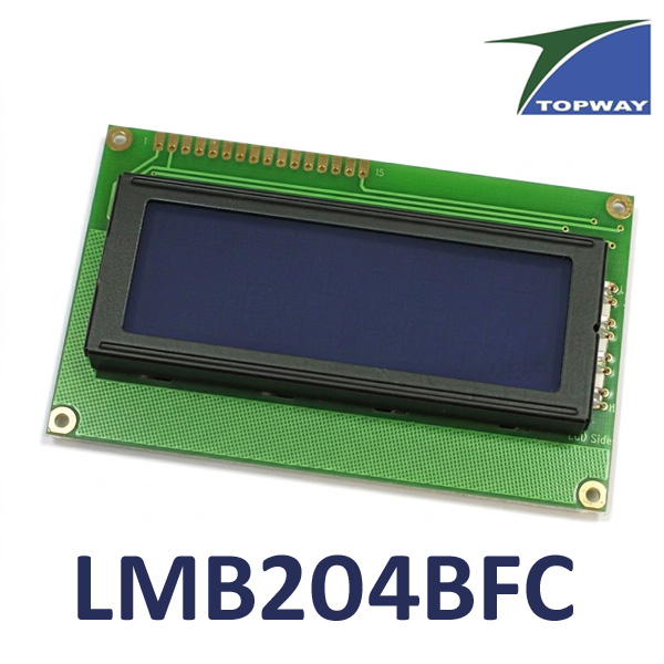
LMB204BFC Character LCD 4x20 TOPWAY
Industrial-Grade LCD
Blue Backlight
مرجع داخلي:
LMB204BFC
Product Description
The TOPWAY LMB204BFC is a 20×4 character LCD module designed for embedded electronic systems, industrial control panels, measurement instruments, and microcontroller-based applications.
It features an STN (Super Twisted Nematic) negative transmissive LCD panel with a white LED backlight. The display provides four lines of text, with 20 characters per line, using a 5×8 dot character matrix. It displays light gray characters against a deep blue background.
The module uses an ST7066U or equivalent LCD controller together with ST7063C or equivalent segment drivers. It supports both 4-bit and 8-bit parallel communication modes, allowing integration with compatible microcontrollers and embedded control systems.
Operating from a 5V DC supply, the LMB204BFC supports standard character-display functions, including cursor positioning, display shifting, text positioning, and user-defined characters. Its Character Generator RAM (CGRAM) allows developers to create up to eight custom 5×8 dot characters.
The module includes a white LED backlight consisting of four LEDs and an adjustable contrast input that requires an external 5kΩ variable resistor.
With its 98 × 60mm outline, 16-pin connector, and four mounting holes, the LMB204BFC is suitable for electronic equipment requiring a 20×4 text display.
Specifications
| Parameter | Specification |
|---|---|
| Manufacturer | TOPWAY Technology |
| Model | LMB204BFC |
| Product Type | Character LCD Module |
| Display Format | 20 Characters × 4 Lines |
| Character Matrix | 5 × 8 Dots |
| Display Technology | STN |
| Display Mode | Negative, Transmissive |
| Character Color | Light Gray |
| Background Color | Deep Blue |
| Viewing Direction | 6H |
| Driving Method | 1/16 Duty |
| Bias Ratio | 1/5 Bias |
| LCD Controller | ST7066U or equivalent |
| Segment Drivers | ST7063C or equivalent |
| Communication Interface | 4-bit / 8-bit Parallel |
| Logic Supply Voltage | 4.7–5.3V DC |
| Typical Supply Voltage | 5.0V DC |
| Operating Current | 1.5mA typical, 3.5mA maximum |
| Backlight Type | White LED |
| Number of Backlight LEDs | 4 |
| Backlight Forward Voltage | 5.0V typical |
| Backlight Test Current | 68mA |
| Maximum Backlight Current | 80mA |
| Contrast Adjustment | External 5kΩ variable resistor |
| Outline Dimensions | 98.0 × 60.0 × 13.7mm maximum |
| Connector | 16-pin Parallel Interface |
| Connector Pitch | 2.54mm |
| Mounting Holes | 4 × Ø2.5mm |
| Operating Temperature | -20°C to +70°C |
| Storage Temperature | -30°C to +80°C |
Technical Information
1. Display Technology and Character Format
The LMB204BFC uses an STN negative transmissive LCD panel.
Its display format provides 20 characters per line across four lines, with each character represented by a 5×8 dot matrix.
| Display Parameter | Specification |
|---|---|
| Display Format | 20 × 4 Characters |
| Character Matrix | 5 × 8 Dots |
| LCD Technology | STN |
| Display Mode | Negative / Transmissive |
| Character Color | Light Gray |
| Background Color | Deep Blue |
| Viewing Direction | 6H |
| Driving Duty | 1/16 |
| Bias Ratio | 1/5 |
| Backlight | White LED |
The negative display configuration uses light gray characters against a deep blue background. The manufacturer notes that the exact color tone may vary slightly with temperature and driving conditions.
2. LCD Controller and Segment Drivers
The module incorporates an ST7066U or equivalent LCD controller and ST7063C or equivalent segment drivers.
The controller supports:
- Display ON/OFF control.
- Cursor positioning and blinking.
- Display shifting.
- Character writing and reading.
- Display clearing.
- Return-home operation.
- Custom character generation.
- 4-bit and 8-bit communication modes.
The controller and segment drivers manage the 20×4 character display using a 1/16 duty and 1/5 bias driving configuration.
3. Parallel Communication Interface
The LMB204BFC uses a standard 16-pin parallel interface and supports both 4-bit and 8-bit communication.
| Pin | Signal | Function |
|---|---|---|
| 1 | VSS | Ground (0V) |
| 2 | VDD | Positive power supply |
| 3 | V0 | LCD contrast reference |
| 4 | RS | Register Select |
| 5 | R/W | Read / Write control |
| 6 | E | Data Enable |
| 7 | DB0 | Data Bus Bit 0 |
| 8 | DB1 | Data Bus Bit 1 |
| 9 | DB2 | Data Bus Bit 2 |
| 10 | DB3 | Data Bus Bit 3 |
| 11 | DB4 | Data Bus Bit 4 |
| 12 | DB5 | Data Bus Bit 5 |
| 13 | DB6 | Data Bus Bit 6 |
| 14 | DB7 | Data Bus Bit 7 |
| 15 | BLA | Backlight Positive Supply |
| 16 | BLK | Backlight Negative Supply |
4-Bit Communication Mode
In 4-bit mode, only DB4–DB7 are used for data communication. Pins DB0–DB3 are left open, as specified by the manufacturer.
This configuration reduces the number of microcontroller pins required.
8-Bit Communication Mode
In 8-bit mode, all eight data lines (DB0–DB7) are used for communication.
The main control signals operate as follows:
- RS = HIGH: Display data.
- RS = LOW: Instruction data.
- R/W = HIGH: Read operation.
- R/W = LOW: Write operation.
- E: Data enable signal.
4. Electrical Characteristics
The LCD logic operates from a regulated 5V DC supply.
| Parameter | Minimum | Typical | Maximum |
|---|---|---|---|
| Operating Voltage | 4.7V | 5.0V | 5.3V |
| Operating Current | — | 1.5mA | 3.5mA |
| Input High Voltage | 0.8 × VDD | — | VDD |
| Input Low Voltage | 0V | — | 0.5V |
The LCD logic current does not include the LED backlight current.
The manufacturer's absolute maximum supply-voltage rating is 6.0V. This is a stress limit, not a recommended operating voltage.
5. White LED Backlight
The LMB204BFC features a white LED backlight consisting of four LEDs, as shown in the manufacturer's backlight circuit diagram.
| Backlight Parameter | Specification |
|---|---|
| Backlight Color | White |
| Number of LEDs | 4 |
| Forward Voltage | 5.0V typical |
| Test Current | 68mA |
| Maximum Forward Current | 80mA |
| Positive Terminal | BLA |
| Negative Terminal | BLK |
The backlight uses separate positive and negative power connections through pins 15 and 16.
The manufacturer warns that exceeding the specified backlight driving current may damage the LEDs or shorten their operating lifetime.
6. Contrast Adjustment
The LMB204BFC provides a V0 terminal for adjusting LCD contrast.
An external variable resistor is required to supply the contrast reference voltage.
The manufacturer recommends a 5kΩ variable resistor.
Adjusting this resistor changes the contrast between the displayed characters and background.
7. Display Memory and Custom Characters
The module contains two principal display memory areas:
- Display Data RAM (DDRAM): Stores the character codes displayed on the LCD.
- Character Generator RAM (CGRAM): Stores user-defined character patterns.
The CGRAM supports up to eight custom characters, each using a 5×8 dot matrix.
These custom characters can be used to display application-specific symbols, indicators, and simple icons.
8. Display Memory Address Mapping
The manufacturer specifies the following DDRAM starting addresses for the four display lines:
| Display Line | Starting Address | Ending Address |
|---|---|---|
| Line 1 | 00h | 13h |
| Line 2 | 40h | 53h |
| Line 3 | 14h | 27h |
| Line 4 | 54h | 67h |
This memory arrangement is important when positioning text on the four display lines.
The module uses the controller's two-line addressing configuration internally to support its four physical display rows.
9. Initialization and Reset
The LCD module performs an automatic reset routine when power is applied.
According to the manufacturer, the reset process takes approximately 80ms.
After reset, the controller defaults to:
- 8-bit interface mode.
- One-line display configuration.
- 5×8 dot character font.
- Display OFF.
- Cursor OFF.
- Cursor blinking OFF.
- Incremental address mode.
- No display shifting.
For normal operation, the manufacturer specifies:
- N = 1: Two-line controller configuration.
- F = 0: 5×8 dot font.
- D = 1: Display ON.
These settings must be applied during initialization.
10. Mechanical Dimensions
The module has a compact rectangular design with four mounting holes.
| Parameter | Specification |
|---|---|
| Overall Width | 98.0mm |
| Overall Height | 60.0mm |
| Maximum Thickness | 13.7mm |
| Viewing Area | 76.0 × 25.2mm |
| Active Area | 70.4 × 20.8mm |
| Mounting Holes | 4 × Ø2.5mm |
| Connector | 16-pin |
| Connector Pitch | 2.54mm |
The separate mechanical outline drawing provides the mounting-hole positions, connector layout, panel wiring details, and pixel dimensions.
Features
- 20×4 Character Display: Displays 20 characters per line across four lines.
- 5×8 Dot Character Format: Supports alphanumeric characters and symbols.
- STN Negative LCD: Uses negative transmissive display technology.
- Light Gray Characters: Deep blue background for clear visual contrast.
- White LED Backlight: Four LEDs provide display illumination.
- ST7066U Controller: Uses an ST7066U or equivalent LCD controller.
- 4-Bit / 8-Bit Interface: Supports two parallel communication modes.
- Custom Characters: Supports up to eight user-defined characters.
- 5V Operation: Designed for conventional 5V embedded electronic systems.
- Adjustable Contrast: Uses an external 5kΩ variable resistor.
- Compact Mounting Design: Four mounting holes for panel integration.
- Wide Operating Temperature: Supports operation from -20°C to +70°C.
Applications
- Industrial control panels.
- Embedded electronic systems.
- Digital measurement instruments.
- Electronic testing equipment.
- Microcontroller-based projects.
- Arduino-based projects.
- Power supply monitoring systems.
- Temperature and humidity monitoring devices.
- Industrial automation equipment.
- Equipment status and menu displays.
Frequently Asked Questions (FAQ)
1. What is the display format of the TOPWAY LMB204BFC?
The LMB204BFC is a 20×4 character LCD module, providing 20 characters per line across four lines, with a 5×8 dot character format.
2. Is the LMB204BFC a graphic LCD or a character LCD?
It is a character LCD designed to display alphanumeric characters, numbers, symbols, and user-defined characters rather than unrestricted pixel-level graphics.
3. What type of LCD technology does it use?
It uses STN negative transmissive LCD technology, with light gray characters and a deep blue background.
4. What is the operating voltage?
The specified operating voltage range is 4.7–5.3V DC, with a typical supply voltage of 5V.
5. Does the LMB204BFC support 4-bit and 8-bit communication?
Yes. It supports both modes. In 4-bit mode, DB4–DB7 are used, while 8-bit mode uses the complete DB0–DB7 data bus.
6. Does the display include a backlight?
Yes. It includes a white LED backlight consisting of four LEDs. The datasheet specifies a typical forward voltage of 5V, a test current of 68mA, and a maximum forward current of 80mA.
7. Can I create custom characters on the LMB204BFC?
Yes. The module supports up to eight user-defined 5×8 dot characters through its Character Generator RAM (CGRAM).
8. Is the LMB204BFC compatible with Arduino?
It can be interfaced with compatible Arduino boards through its 4-bit or 8-bit parallel interface. The controller must provide the appropriate 5V logic signals and initialization commands.