


Product Description
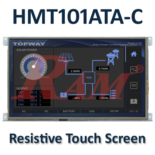
The TOPWAY HMT101ATA-C is a 10.1-inch Smart TFT LCD module featuring an integrated 32-bit MCU and graphics engine, designed for industrial control systems, instrumentation, medical electronics, and power equipment applications.
With a 1024 × 600 pixel resolution and 65K colors (16-bit), this module provides a clear graphical display for equipment monitoring, control panels, and embedded user interfaces. It features a resistive touchscreen, allowing users to interact with displayed menus, buttons, and graphical elements.
Unlike conventional TFT displays that require the host controller to generate and manage all graphical content, the HMT101ATA-C includes an onboard display function controller and graphics engine. It supports TOPWAY TML files, allowing graphical interfaces, pictures, and icons to be designed in advance and stored in the module's internal Flash memory.
Communication with an external host controller is handled through a UART interface, allowing the host to send commands, update displayed values, and receive touch-key information. A separate USB interface is provided for downloading TML projects and image files.
The HMT101ATA-C is suitable for embedded applications that require a programmable graphical interface while reducing the processing and display-management workload of the main controller.
Specifications
| Parameter | Specification |
|---|---|
| Manufacturer | TOPWAY Technology |
| Model | HMT101ATA-C |
| Product Type | Smart TFT LCD Module |
| Screen Size | 10.1 inches |
| Resolution | 1024 × 600 pixels |
| Color Depth | 65K colors (16-bit) |
| Pixel Configuration | RGB Stripe |
| Display Mode | Transmissive / Normal Black |
| Viewing Direction | 6H / 12H, depending on display content |
| Active Area | 222.72 × 125.28 mm |
| Overall Dimensions | 251.0 × 140.0 × 19.1 mm |
| Touch Panel | Resistive Touch Panel |
| Backlight | LED |
| Surface Treatment | Anti-Glare |
| Onboard Controller | 32-bit MCU |
| Graphics Engine | Integrated display graphics engine |
| Display Interface | UART |
| USB Interface | USB for project and image downloading |
| Default Communication Protocol | TOPWAY SMART LCD Command Protocol |
| Default Communication Settings | 115200 bps, 8N1 |
| Operating Voltage | 11–26V DC |
| Typical Supply Voltage | 12V DC |
| Operating Current | 350mA typical |
| Operating Temperature | -20°C to +70°C |
| Storage Temperature | -30°C to +80°C |
Technical Information
1. Display and Touchscreen
The HMT101ATA-C features a 10.1-inch TFT LCD with a resolution of 1024 × 600 pixels and 65K colors (16-bit).
| Display Parameter | Specification |
|---|---|
| Screen Size | 10.1 inches |
| Resolution | 1024 × 600 |
| Color Depth | 16-bit / 65K colors |
| Display Mode | Transmissive / Normal Black |
| Pixel Arrangement | RGB Stripe |
| Active Area | 222.72 × 125.28 mm |
| Backlight | LED |
| Surface Treatment | Anti-Glare |
| Touch Technology | Resistive |
The resistive touchscreen supports user interaction through the module's predefined graphical interface.
2. Integrated MCU and Graphics Engine
The module incorporates an onboard 32-bit MCU and a dedicated display function controller with a graphics engine.
This allows the module to handle graphical interface operations internally, reducing the amount of display-related processing required from the external host controller.
Its graphics system supports pre-designed TML interface files, pictures, and icons stored in internal Flash memory.
3. TOPWAY TML Graphical Interface
The HMT101ATA-C supports TOPWAY TML files for creating and managing graphical user interfaces.
The general workflow is:
- Design the graphical interface using the TOPWAY Graphics Editor.
- Import pictures and create the user interface flow.
- Download the TML project and image files to the display through USB.
- Power on the module to run the stored graphical interface.
- Connect the external host through UART to exchange real-time data and commands.
The stored TML files define the interface flow and touch response, allowing the display to operate as a standalone graphical interface while exchanging data with the host controller.
4. UART Communication Interface
The UART interface (K1) is used for communication between the HMT101ATA-C and an external host controller.
It supports sending commands and data to the display and receiving information such as touch-key responses.
The connector provides:
| Pin | Signal | Function |
|---|---|---|
| 1, 2 | VDD | Power Supply |
| 3 | RTS (BUSY) | Busy Status Output |
| 4 | TX | Data Output |
| 5, 6 | RX | Data Input |
| 7, 8 | GND | Ground |
The RTS signal functions as a busy indicator:
- Logic 1: Busy.
- Logic 0: Not busy.
Hardware handshaking is recommended by the manufacturer.
Important: Although the product manual refers to this interface as UART, the electrical characteristics and included SMART LCD Command Manual specify RS232-C communication levels. It should not be connected directly to a 3.3V or 5V TTL UART without an appropriate interface.
5. USB Interface
The USB interface (K2) is used to preload TML project files and image files into the module.
| Pin | Signal | Function |
|---|---|---|
| 1 | VUSB | USB Power |
| 2 | D- | USB Data Negative |
| 3 | D+ | USB Data Positive |
| 4 | ID | USB Host/Client Identification |
| 5 | GND | Ground |
The USB interface supports project and image file downloading.
Important: The manufacturer specifically warns not to connect the USB terminal while the VDD supply at K1 is present. Follow the manual's connection instructions when programming the display.
6. Memory and Data Handling
The HMT101ATA-C uses internal Flash memory and RAM to manage graphical resources and real-time data.
- TML interface files, pictures, and icons are stored in Flash memory.
- Custom memory is stored in Flash and can be accessed through UART.
- VP variables are stored in RAM and support real-time data exchange with the host.
- The display controller processes host commands and reports touch-key information.
The manual specifies the following memory allocation:
| Memory Function | Memory Name | Allocated Space |
|---|---|---|
| 128-byte String | VP_STR | 128KB |
| 16-bit Number | VP_N16 | 64KB |
| 32-bit Number | VP_N32 | 64KB |
| 64-bit Number | VP_N64 | 64KB |
| 16-bit Graphic Data Array | VP_G16 | 128KB |
| Bitmap Data | VP_BP1 | 128KB |
| Customer Flash | Cust_Flash | 256KB |
| User Binary | USR_bin | 256KB |
7. SMART LCD Command Protocol
The included TOPWAY SMART LCD Command Manual (Protocol V5.04) describes the communication protocol used by the module.
The default serial communication configuration is:
- Baud rate: 115200 bps.
- Data format: 8N1.
- Communication standard: RS232-C.
Supported command functions include:
- Reading module handshake and firmware version.
- Reading the current display page ID.
- Displaying predefined pages.
- Reading touch responses.
- Writing and reading numerical values and strings.
- Controlling backlight brightness.
- Touch-panel calibration.
- Reading and setting RTC values.
- Accessing internal Flash memory.
The backlight brightness control supports 64 levels.
Optical Characteristics
The manufacturer provides the following typical optical performance values:
| Parameter | Specification |
|---|---|
| Luminance | 300 cd/m² |
| Contrast Ratio | 800:1 typical |
| Viewing Angle – Top | 75° typical |
| Viewing Angle – Bottom | 80° typical |
| Viewing Angle – Left | 80° typical |
| Viewing Angle – Right | 80° typical |
| Response Time – TON | 7ms typical |
| Response Time – TOFF | 9ms typical |
| Luminance Uniformity | 80% typical |
| NTSC Color Gamut | 50% typical |
Optical measurements are specified at 25°C under the manufacturer's test conditions.
Electrical Characteristics
| Parameter | Specification |
|---|---|
| Minimum Operating Voltage | 11V DC |
| Typical Operating Voltage | 12V DC |
| Maximum Operating Voltage | 26V DC |
| Operating Current | 350mA typical |
| Battery Supply Current | 0.6µA typical |
| Absolute Maximum Supply Voltage | 28V |
The typical operating current is specified under normal display conditions with USB disconnected.
Features
- 10.1-Inch TFT Display: Large display area with 1024 × 600 resolution.
- 65K Colors: 16-bit color depth for graphical user interfaces.
- Resistive Touchscreen: Supports interactive menus and touch-based controls.
- Integrated 32-bit MCU: Onboard processing for display and graphical operations.
- Built-in Graphics Engine: Handles display drawing and graphical interface operations.
- TOPWAY TML Support: Pre-designed graphical interfaces can be stored and executed by the module.
- UART Communication: Enables real-time data exchange with an external host controller.
- USB Project Download: Supports loading TML files, pictures, and icons.
- Internal Flash and RAM: Provides storage for graphical resources and application data.
- Touch-Key Reporting: Sends touch interaction information to the host controller.
- 64-Level Backlight Control: Allows brightness adjustment through commands.
- Wide Operating Temperature: Supports operation from -20°C to +70°C.
Applications
- Industrial control panels.
- Machine monitoring and control systems.
- Industrial instrumentation.
- Power electronics equipment.
- Embedded system user interfaces.
- Measurement and testing equipment.
- Medical electronic equipment, subject to appropriate system-level qualification.
- Automation equipment.
- Smart control terminals.
- Custom graphical interfaces for microcontroller-based projects.
Frequently Asked Questions (FAQ)
1. What is the TOPWAY HMT101ATA-C?
The HMT101ATA-C is a 10.1-inch Smart TFT LCD module with an integrated 32-bit MCU and graphics engine. It supports pre-designed graphical interfaces and communication with an external host controller.
2. What is the display resolution?
It features a 10.1-inch TFT display with a resolution of 1024 × 600 pixels and 65K colors (16-bit).
3. Does the HMT101ATA-C have a touchscreen?
Yes. It includes a resistive touchscreen for interacting with graphical menus, buttons, and other predefined interface elements.
4. Can this display operate without an external controller?
It can execute its preloaded TML graphical interface independently. However, an external host controller is used when the application requires real-time data exchange and control through UART.
5. How do I create and upload a graphical interface?
The manufacturer specifies using the TOPWAY Graphics Editor to design the interface, import pictures, and create the interface flow. The resulting TML and image files are downloaded to the module through its USB interface.
6. What communication interface does the HMT101ATA-C use?
It uses a UART-labelled interface (K1) for host communication. The manufacturer's electrical specifications identify RS232-C signal levels, and the default communication configuration is 115200 bps, 8N1.
7. What is the operating voltage of the HMT101ATA-C?
The specified operating voltage range is 11–26V DC, with a typical supply voltage of 12V DC. Its typical operating current is 350mA.
8. Can I connect the HMT101ATA-C directly to an Arduino or ESP32?
Not directly through a standard TTL UART connection. The module's communication electrical characteristics are specified for RS232-C levels. An appropriate RS232-to-TTL level converter is required when interfacing with Arduino, ESP32, or other TTL-based microcontrollers.