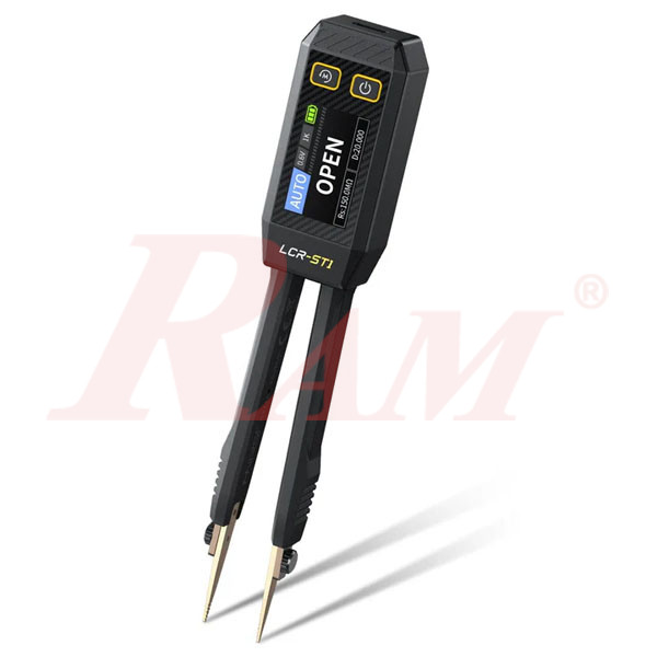




FNIRSI® LCR-ST1 Mini Smart Digital Tweezer LCR SMD ESR Tester
Product Description
The FNIRSI® LCR-ST1 is a compact, multifunctional digital tweezer LCR tester designed for measuring electronic components, particularly small SMD components and parts in confined spaces. Its tweezer-style design allows users to grip component terminals directly, making it convenient for electronics repair, PCB inspection, laboratory work, and component testing.
The LCR-ST1 supports automatic measurement of resistance, capacitance, inductance, and diodes. It offers three selectable test frequencies of 100Hz, 1kHz, and 10kHz, along with two selectable RMS test voltage levels of 0.3V and 0.6V to suit different component measurements.
With a 1.14-inch color display, the instrument presents primary measurement values and auxiliary parameters. Depending on the measurement mode, it can display parameters such as ESR, D (dissipation factor), Q (quality factor), Z (impedance), and X (reactance).
The tester features automatic component recognition, data hold, and data storage with export to a PC through its USB Type-C data connection. Its built-in 250mAh rechargeable lithium battery, magnetic adsorption feature, and replaceable tweezer heads make it a practical tool for technicians and engineers working with electronic components.
Key Features
- Multifunction LCR Testing: Measures resistance, capacitance, inductance, and diode forward voltage.
- Automatic Component Recognition: Automatically identifies supported component types and selects the corresponding measurement mode.
- Three Test Frequencies: Selectable 100Hz, 1kHz, and 10kHz test frequencies.
- Two Test Voltage Levels: Selectable 0.3V and 0.6V RMS test levels.
- Multiple Measurement Parameters: Displays ESR, D (dissipation factor), Q (quality factor), Z (impedance), and X (reactance) as applicable.
- SMD Tweezer Design: Allows convenient contact with small electronic components and terminals in confined spaces.
- 1.14-Inch Color Display: Shows measurement values, test settings, battery level, and auxiliary parameters.
- Replaceable Tweezer Heads: Supports interchangeable test heads for different component-testing requirements.
- Data Hold Function: Freezes the displayed measurement result for easier reading.
- Data Storage and PC Export: Automatically saves measurement records and allows stored data to be viewed and exported through a computer.
- Short-Circuit Zeroing: Supports measurement zeroing using a short-circuit connection at the selected test frequency.
- Rechargeable Battery: Built-in 250mAh lithium battery with USB Type-C charging.
- Adjustable Settings: Includes language selection, volume adjustment, screen brightness, automatic power-off, and factory reset.
Technical Specifications
General Specifications
| Parameter | Specification |
|---|---|
| Brand | FNIRSI |
| Model | LCR-ST1 |
| Display | 1.14-Inch Color Screen |
| Battery | 250mAh Rechargeable Lithium Battery |
| Charging Interface | USB Type-C |
| Charging Specification | 5V / 1A |
| Dimensions | 28 × 19 × 150mm |
| Weight | 41g |
| Supported Languages | English, Chinese |
| Auto Power-Off | Off / 5 / 15 / 30 minutes |
| Data Transfer | USB Type-C |
| Firmware Upgrade | Supported |
Measurement Specifications
| Measurement Type | Range | Test Frequencies |
|---|---|---|
| Capacitance | 1pF–22mF | 100Hz / 1kHz / 10kHz |
| Inductance | 1µH–10H | 100Hz / 1kHz / 10kHz |
| Resistance | 10mΩ–10MΩ | 100Hz / 1kHz / 10kHz |
| Diode | Forward voltage drop below 0.7V | Diode mode |
Capacitance Measurement Accuracy
| Capacitance Range | 100Hz | 1kHz | 10kHz |
|---|---|---|---|
| 1mF–22mF | ±(5% + 3 digits) | ±(5% + 3 digits) | Not specified |
| 1µF–1mF | ±(2% + 3 digits) | ±(2% + 3 digits) | ±(2% + 3 digits) |
| 1nF–1µF | ±(2% + 3 digits) | ±(0.5% + 3 digits) | ±(0.5% + 3 digits) |
| 1pF–1nF | Not specified | ±(2% + 3 digits) | ±(2% + 3 digits) |
Inductance Measurement Accuracy
| Inductance Range | 100Hz | 1kHz | 10kHz |
|---|---|---|---|
| 1H–10H | ±(5% + 3 digits) | ±(5% + 3 digits) | Not specified |
| 1mH–1H | ±(2% + 3 digits) | ±(2% + 3 digits) | ±(2% + 3 digits) |
| 10µH–1mH | ±(2% + 3 digits) | ±(0.5% + 3 digits) | ±(0.5% + 3 digits) |
| 1µH–10µH | Not specified | Not specified | ±(2% + 3 digits) |
Resistance Measurement Accuracy
| Resistance Range | 100Hz | 1kHz | 10kHz |
|---|---|---|---|
| 1MΩ–10MΩ | ±(5% + 3 digits) | ±(5% + 3 digits) | Not specified |
| 1kΩ–1MΩ | ±(1% + 3 digits) | ±(0.5% + 3 digits) | ±(1% + 3 digits) |
| 1Ω–1kΩ | ±(1% + 3 digits) | ±(0.5% + 3 digits) | ±(0.5% + 3 digits) |
| 10mΩ–1Ω | ±(2% + 3 digits) | ±(2% + 3 digits) | ±(2% + 3 digits) |
Additional Measurement Settings
| Parameter | Specification |
|---|---|
| Test Frequencies | 100Hz / 1kHz / 10kHz |
| Test Voltage Levels | 0.3V RMS / 0.6V RMS |
| Diode Forward Voltage | Below 0.7V |
| Auxiliary Parameters | ESR, D, Q, Z, X |
| Continuity Indication | Resistance below 50Ω in diode mode |
| Short-Circuit Zeroing | Supported |
Applications
- SMD Component Testing: Measuring small surface-mount resistors, capacitors, inductors, and diodes.
- PCB Inspection: Checking electronic components during circuit-board troubleshooting and maintenance.
- Electronics Repair: Identifying and measuring components during repair of electronic equipment.
- Capacitor Testing: Measuring capacitance and viewing auxiliary parameters such as ESR and dissipation factor.
- Inductor Testing: Measuring inductance across a wide range of values and selectable test frequencies.
- Resistance Measurement: Checking resistors and other resistive components from milliohm to megaohm ranges.
- Diode Testing: Checking diode forward voltage in diode measurement mode.
- Laboratory and R&D Work: Performing component measurements during electronic circuit development and testing.
Package Contents
- FNIRSI LCR-ST1 Smart Tweezer × 1
- Hook Head (One Pair) × 1
- Magnetic Patch × 1
- USB Data Cable × 1
- User Manual × 1
- Tool Bag × 1
- Packing Box × 1
Frequently Asked Questions (FAQ)
1. What components can the FNIRSI LCR-ST1 measure?
The LCR-ST1 measures resistance, capacitance, inductance, and diode forward voltage. It is particularly suitable for testing small SMD electronic components.
2. What are the measurement ranges of the LCR-ST1?
Its specified measurement ranges are 10mΩ–10MΩ for resistance, 1pF–22mF for capacitance, and 1µH–10H for inductance. It also supports diode testing for forward voltage drops below 0.7V.
3. What test frequencies does the LCR-ST1 support?
It supports three selectable test frequencies: 100Hz, 1kHz, and 10kHz. The available measurement frequency can affect the result, particularly for components with non-ideal characteristics.
4. Can I adjust the test voltage?
Yes. The LCR-ST1 provides two selectable RMS test voltage levels: 0.3V and 0.6V.
5. Does the LCR-ST1 measure capacitor ESR?
The FNIRSI product page lists ESR among its displayed measurement parameters. The instrument also supports capacitance measurement and auxiliary parameter display, including D, Q, Z, and X values.
6. Can the LCR-ST1 automatically identify components?
Yes. It supports automatic recognition and measurement of supported components. However, automatic mode does not support diode measurement, so diode testing should be performed using the dedicated diode mode.
7. Can measurement records be transferred to a computer?
Yes. The tester automatically saves measurement records. Connect it to a computer using a USB Type-C data cable to access the stored data through a simulated USB drive and view or export the records in Excel format.
8. Can the LCR-ST1 measure components while they are still installed on a PCB?
The manufacturer does not recommend in-circuit measurements. External PCB connections can affect the results, and measurements taken under these conditions are for reference only without guaranteed accuracy. The component should be isolated when accurate measurements are required.
Download: