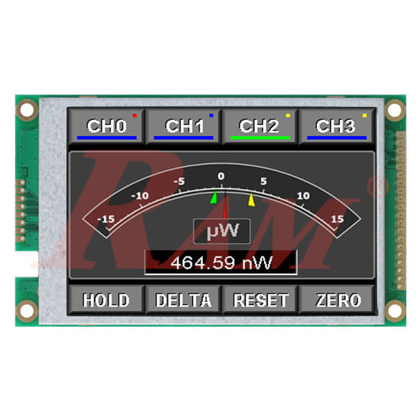
LMT035DNJFWD-NAN 3.5-inch TFT Color LCD Module TOPWAY
480x320 Color TFT
Display Controller ILI9488 or equivalent
Internal Reference:
LMT035DNJFWD.NAN
Product Description
The TOPWAY LMT035DNJFWD-NAN is a 3.5-inch TFT color LCD module designed for embedded systems, industrial control equipment, portable instruments, and microcontroller-based applications.
Featuring a 480 × 320 pixel resolution and support for 65K or 262K colors, this display provides a compact, high-resolution graphical interface for presenting measurements, menus, icons, status information, and other visual content.
The module uses an a-Si TFT active-matrix panel with a transmissive, normally white display mode and RGB stripe pixel configuration. It is driven by an ILI9488 or equivalent TFT controller.
One of its key advantages is interface flexibility. The module supports an 8-bit parallel interface as the default configuration, with alternative 3-wire and 4-wire SPI configurations available through hardware resistor selection. This allows integration into different embedded hardware designs, depending on the required communication interface.
Operating with a 5V main supply and a separate 3.3V typical logic supply, the LMT035DNJFWD-NAN features an integrated LED backlight with typical luminance of 250cd/m². Its 28-position K1 terminal provides the display's power, control, data, and backlight signals.
Specifications
| Parameter | Specification |
|---|---|
| Manufacturer | TOPWAY Technology |
| Model | LMT035DNJFWD-NAN |
| Product Type | TFT Color LCD Module |
| Screen Size | 3.5 inches |
| Resolution | 480 × 320 pixels |
| Color Depth | 65K / 262K colors |
| Display Technology | a-Si TFT Active Matrix |
| Display Mode | Transmissive / Normally White |
| Pixel Configuration | RGB Stripe |
| Display Controller | ILI9488 or equivalent |
| Default Interface | 8-bit Parallel |
| Alternative Interfaces | 3-wire SPI, 4-wire SPI |
| Main Supply Voltage (VDD) | 4.8–5.2V DC |
| Typical Main Supply | 5.0V DC |
| Logic Supply (IOVCC) | 2.5–3.3V DC operating range indicated in interface timing notes |
| Typical Logic Voltage | 3.3V DC |
| Operating Current, Backlight ON | 105mA typical |
| Operating Current, Backlight OFF | 4.8mA typical |
| Active Display Area | 48.96 × 73.44mm |
| Pixel Pitch | 0.153 × 0.153mm |
| Backlight Type | LED |
| Backlight Control | BLEN input |
| Typical Luminance | 250cd/m² |
| Viewing Direction | 3 o'clock / 9 o'clock, depending on content |
| Typical Contrast Ratio | 500:1 |
| Typical Response Time | 25ms |
| Maximum Response Time | 35ms |
| Typical NTSC Color Gamut | 60% |
| Operating Temperature | -20°C to +70°C |
| Storage Temperature | -30°C to +80°C |
| Overall Dimensions | Approximately 97.5 × 58.0mm, according to mechanical drawing |
| Connector | 28-position K1 terminal |
Technical Information
1. Display Technology and Resolution
The LMT035DNJFWD-NAN uses an a-Si TFT active-matrix display panel with RGB stripe pixel configuration.
| Display Parameter | Specification |
|---|---|
| Screen Size | 3.5 inches |
| Resolution | 480 × 320 pixels |
| Color Depth | 65K / 262K colors |
| Display Technology | TFT Active Matrix |
| Display Mode | Transmissive / Normally White |
| Pixel Configuration | RGB Stripe |
| Active Display Area | 48.96 × 73.44mm |
| Pixel Pitch | 0.153 × 0.153mm |
| Polarizer Surface Treatment | HC |
The 480 × 320 resolution provides 153,600 pixels, making the display suitable for detailed graphical interfaces, measurement readings, icons, menus, and embedded control applications.
2. Display Controller
The module uses an ILI9488 or equivalent TFT driver.
The controller manages display initialization, pixel data transfer, memory access, and display configuration.
Supported display functions include:
- Software and hardware reset.
- Display identification and status reading.
- Sleep mode and display ON/OFF control.
- Display inversion.
- Column and row address configuration.
- Memory read and write.
- Partial display mode.
- Vertical scrolling.
- Display brightness control.
- Display power and color configuration.
- Gamma adjustment and related display commands.
3. Supported Communication Interfaces
The LMT035DNJFWD-NAN supports three hardware interface configurations:
| Interface Mode | Description | Configuration |
|---|---|---|
| 8-bit Parallel | 8-bit DBI Type B interface | Default |
| 3-wire SPI | Serial communication using clock and data signals | Hardware resistor selection required |
| 4-wire SPI | Serial communication with separate data/command selection | Hardware resistor selection required |
8-bit Parallel Interface
The default configuration uses an 8-bit data bus with the following signals:
- D0–D7: Parallel data bus.
- /CS: Active-low chip select.
- /WR: Active-low write enable.
- /RD: Active-low read enable.
- D/C: Data/command selection.
- /RES: Active-low reset.
- FMARK: Display timing frame signal.
The datasheet also describes RGB pixel-data transfer using:
- 16-bit RGB 5-6-5 format for 65K colors.
- 18-bit RGB 6-6-6 format for 262K colors.
Both formats are transferred using the 8-bit data bus.
3-wire SPI Interface
The 3-wire SPI configuration uses:
- SCL: Serial clock.
- SDA: Serial data input/output.
- /CS: Chip select.
In this configuration, the /RD and /WR(D/C) pins must be fixed at the IOVCC level, according to the manufacturer's terminal-function table.
4-wire SPI Interface
The 4-wire SPI configuration uses:
- SCL: Serial clock.
- SDA: Serial data.
- /CS: Chip select.
- D/C: Data/command selection.
In this configuration, the /RD pin must be fixed at IOVCC, while the /WR(D/C) pin functions as the display data/command selection signal.
Hardware Interface Selection
The interface is selected through hardware resistor positions on the module PCB.
| Mode | Resistors to Install | Resistors Not Installed |
|---|---|---|
| 8-bit Parallel (Default) | R23, R24 | R22, R25 |
| 3-wire SPI | R22, R25, R7, R8, R9, R10 | R23, R24, R2, R3 |
| 4-wire SPI | R22, R24, R7, R8, R9, R10, R11 | R23, R25, R2, R3 |
The SPI interface configuration therefore requires hardware modification or the correct factory configuration. It should not be assumed that every supplied module can switch interfaces through software alone.
4. Electrical Characteristics
The module uses a 5V main supply and a separate logic supply.
| Parameter | Minimum | Typical | Maximum |
|---|---|---|---|
| Main Supply (VDD) | 4.8V | 5.0V | 5.2V |
| Logic Supply (IOVCC) | 2.5V | 3.3V | 3.3V |
| Operating Current, Backlight ON | — | 105mA | — |
| Operating Current, Backlight OFF | — | 4.8mA | — |
The electrical-characteristics table specifies the main supply and operating currents at VDD = 5V and IOVCC = 3.3V.
The logic input levels are referenced to IOVCC:
- Input HIGH: At least 0.7 × IOVCC.
- Input LOW: No more than 0.3 × IOVCC.
The maximum input and output voltage levels are also referenced to IOVCC. Ensure that the host controller's signal levels are compatible with the configured logic supply.
5. LED Backlight and Control
The display includes an integrated LED backlight controlled through the BLEN input.
According to the terminal-function table:
- BLEN = HIGH: Backlight OFF.
- BLEN = LOW: Backlight ON.
The backlight control input also supports PWM brightness control. The manufacturer specifies a PWM frequency between 2kHz and 10kHz.
The optical-characteristics test conditions specify an LED backlight current of 120mA. This is a test condition and should not automatically be treated as the recommended operating current for every application.
6. Optical Characteristics
The LMT035DNJFWD-NAN provides the following optical performance according to the manufacturer's datasheet.
| Parameter | Minimum | Typical | Maximum |
|---|---|---|---|
| Viewing Angle, θT | 60° | 70° | — |
| Viewing Angle, θB | 50° | 60° | — |
| Viewing Angle, θL | 60° | 70° | — |
| Viewing Angle, θR | 60° | 70° | — |
| Contrast Ratio | 400:1 | 500:1 | — |
| Response Time | — | 25ms | 35ms |
| Luminance | 250cd/m² | 250cd/m² | — |
| Luminance Uniformity | 80% | — | — |
| NTSC Color Gamut | — | 60% | — |
The viewing-angle specifications are measured at a contrast ratio of at least 10. The manufacturer identifies different viewing characteristics depending on direction and displayed content.
7. Mechanical Dimensions and Connector
The module is designed for integration into embedded electronic equipment and custom display assemblies.
According to the mechanical drawing:
| Parameter | Specification |
|---|---|
| Overall Width | Approximately 97.5mm |
| Overall Height | Approximately 58.0mm |
| Active Display Area | 48.96 × 73.44mm |
| Bezel Opening | Approximately 77.1 × 51.6mm |
| Metal Frame | Approximately 85.7 × 56.1mm |
| Connector | K1 |
| Connector Positions | 28 positions |
| Mounting Holes | 4 × Ø3.2mm PTH |
| Additional Copper Holes | 4 × Ø5.5mm Cu, as shown in drawing |
The 28-position K1 connector includes the power, backlight, control, and data signals. Pins 20–28 are designated NC in the terminal-function table.
The supplied mechanical drawing should be used when designing the PCB footprint, mounting holes, and enclosure.
8. Operating Temperature and Handling
| Parameter | Specification |
|---|---|
| Operating Temperature | -20°C to +70°C |
| Storage Temperature | -30°C to +80°C |
| Operating Conditions | No condensation |
The manufacturer recommends:
- Applying the correct power-on and power-off sequence.
- Keeping signal lines as short as possible to reduce electrical noise.
- Avoiding prolonged display of an unchanged screen pattern.
- Protecting the module against electrostatic discharge.
- Avoiding mechanical pressure, bending, and twisting.
- Using an appropriate protective enclosure to reduce exposure to strong light.
Features
- 3.5-Inch TFT Color Display: Compact display for embedded graphical interfaces.
- 480 × 320 Resolution: Provides 153,600 pixels for detailed graphics and information.
- 65K / 262K Colors: Supports two color-depth configurations.
- ILI9488 Controller: Uses an ILI9488 or equivalent TFT driver.
- Multiple Interface Options: Supports 8-bit parallel, 3-wire SPI, and 4-wire SPI.
- Hardware Interface Selection: Interface configuration is selected using PCB resistor positions.
- 5V Main Supply: Operates from a typical 5V DC supply.
- 3.3V Logic: Separate logic supply and compatible signal-level requirements.
- Integrated LED Backlight: Typical luminance of 250cd/m².
- PWM Backlight Control: BLEN supports backlight control and PWM brightness adjustment.
- 28-Position Connection: K1 terminal provides the display's electrical connections.
- Wide Operating Temperature: Supports operation from -20°C to +70°C.
Applications
- Embedded graphical user interfaces.
- Industrial control equipment.
- Portable electronic instruments.
- Measurement and monitoring devices.
- Microcontroller-based projects.
- Smart home controllers.
- IoT monitoring systems.
- Electronic control panels.
- Custom embedded display assemblies.
- Electronic product development and prototyping.
Frequently Asked Questions (FAQ)
1. What is the resolution of the TOPWAY LMT035DNJFWD-NAN?
The display has a resolution of 480 × 320 pixels and a diagonal screen size of 3.5 inches.
2. How many colors does this LCD support?
The module supports 65K or 262K colors, depending on the selected pixel-data format.
3. Which display controller does this module use?
The module uses an ILI9488 or equivalent TFT controller.
4. Does the LMT035DNJFWD-NAN support SPI communication?
Yes. It supports both 3-wire and 4-wire SPI interfaces, in addition to its default 8-bit parallel interface. The SPI configurations require the appropriate hardware resistor selection.
5. What is the operating voltage of this LCD?
The main supply operates from 4.8V to 5.2V, with a typical value of 5V. The logic supply is typically 3.3V.
6. What is the brightness of the display?
The manufacturer specifies a luminance of 250cd/m² under its optical measurement conditions.
7. Can the backlight brightness be controlled?
Yes. The BLEN input supports backlight ON/OFF control and PWM brightness adjustment. The specified PWM frequency is between 2kHz and 10kHz.
8. Is the LMT035DNJFWD-NAN suitable for Arduino and ESP32 projects?
It can be integrated into compatible Arduino and ESP32-based designs. The module supports SPI configurations that may be more convenient for microcontrollers with limited GPIO resources, but the hardware interface configuration, logic voltage, controller initialization, and wiring must be compatible with the selected mode.